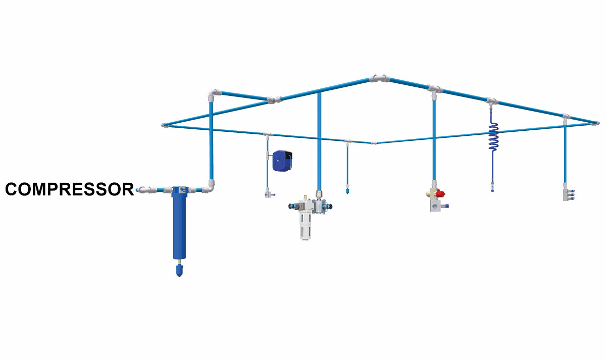
More than 98% of factories using compressed air started out with a dead-end network. Over the years their systems have evolved into a giant octopuses. The result of the dead-end network is a sacrificed air flow in order to maintain the workstation's use of pressure.
The dead-end or tree network

- Air flow must be sacrificed in order to preserve uniform pressure at the workstations.
- The progressive pressure reduces as the distance increases on the central supply line.
- The equipment using the most air flow should be located near the compressor and the other tools requiring less air the furthest.
- The compressed air is not equally distributed
- Difficult to do maintenance on a dead-end network without interrupting the supply of compressed air
- This is not the optimum design.
The octopus network

- Dead-end networks often evolve into octopus networks over time.
- Different airline materials are used with curves, reductions and enlargements (inconsistent diameters). The installation is done with no knowledge of pneumatic standards.
- The result of this network is varying pressure and flow conditions creating many problems.
- Difficult to do maintenance on a dead-end network without interrupting the supply of compressed air
- The solution is to balance air flow and air pressure. The closed-loop network is the ideal distribution of compressed air at all workstations.
The closed-loop network

- This network allows the supply of air to flow through several lines at a time to any workstation.
- The balance between airflow and air pressure is ensured using a single diameter of the hose/pipe.
- This system can be modified. Ball valves permit the isolation of a particular portion to allow repairs, add connections and do periodic maintenance.
- The size of each loop doesn't have to be uniform. It is important to have at least two different supply routes available simultaneously for each feeder pipe/hose.
- This is the ideal compressed air distribution network.
The system design

It is best to start with a shop layout. Designate where and what tools will be used. Determine the placement of the main air supply line. Drop supply lines to where the workstations will be. Know which workstation requires the correct filter, regulator and lubricator.
Remember to incorporate slopes and drops. The 1:100 ratio (for every 100cm, slope by 1cm) in the same direction of airflow. The slope will lead to any condensation toward automatic drains.
Reduce pressure drops, by sizing the air supply line correctly. Pressure drops are unrecoverable and waste energy. A drop in pressure from 6 bar to 5 bar will decrease tool effectivity by 27%. Energy costs will rise if pressure is increased by 1 bar.
Install swan neck drops to each workstation to minimize water contamination.

Whenever maintenance needs to be done, a bypass system should be in place to allow for uninterrupted operation while maintenance or repairs are accomplished. This can be achieved by fitting multiple ball valves.
